Embedded Force-Torque Sensing: From Spec to Integration
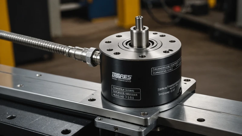
The conventional approach to force-torque sensing in a robot arm is to bolt a six-axis sensor onto the wrist, between the last joint and the end-effector. It works. But when you're building a legged robot where every joint needs to measure contact forces for impedance control, putting a sensor at the wrist doesn't help you at the knee — and wiring six discrete six-axis sensors through a bipedal leg while maintaining IP54 sealing and sub-millisecond latency is an integration problem that most teams never fully solve. Embedding the force-torque sensor inside the joint module changes the problem entirely.
Why Sensor Location Matters More Than Sensor Spec
A force-torque sensor measures the forces and moments at a specific point in the kinematic chain. Placing it at the wrist captures interaction forces with the environment for manipulation tasks, but tells the controller nothing about the internal joint torques at the hip, knee, or ankle. For locomotion, those internal torques are the primary controlled variable — the impedance controller needs to know the torque at each joint output to close the compliance loop.
You can estimate joint torques from a wrist sensor by propagating forces through the Jacobian transpose — in principle. In practice, the kinematic and dynamic model uncertainty in a legged robot running at 1.5 m/s, with significant joint compliance and nonlinear friction in each gearbox stage, makes those estimates noisy. Errors compound at each joint from wrist to hip. The estimate at the hip is substantially less reliable than a direct measurement would be.
Direct sensing at the joint output — downstream of the gearbox — eliminates this uncertainty. The sensor measures what the control loop actually needs: the torque being transmitted to the link, including any deviation from the commanded value due to gearbox friction, inertia, or external loading. This matters for impedance control bandwidth and for accurate contact detection. In our testing, joint-embedded torque sensing enables contact detection latencies below 2 ms; Jacobian-propagated estimates from wrist sensors typically run 10–20 ms latency at the same threshold confidence level.
Sensor Technologies at the Joint Scale
Six-axis force-torque sensing at the joint scale uses one of three underlying measurement principles: strain gauge bridges, capacitive sensing, or optical deflection measurement. Each has distinct tradeoffs for an embedded joint application.
Strain gauge bridge sensors are the most proven technology. A strain gauge rosette applied to a machined elastic element (typically a cross or spoke pattern in the sensor body) measures bending and shear strain, which is converted to force and torque through a calibration matrix. Sensitivities of 0.01–0.1 Nm on the torque axes are achievable in a 40mm format. Temperature coefficient of resistance in the gauge material is the primary drift source; this requires either temperature compensation in the readout circuit or sensor calibration at multiple temperatures. At sub-millisecond SPI readout rates, 16-bit ADC resolution on a 24-bit-capable chip is standard practice.
Capacitive sensors measure deflection of the elastic element by changes in capacitor gap rather than resistive strain. They offer higher sensitivity at small deflections and lower temperature drift than resistive gauges, but the readout circuitry is more complex (capacitance-to-digital converters require careful board layout to minimize parasitic coupling) and the absolute range before saturation is typically narrower. For joints with large torque ranges (100+ Nm), strain gauges remain the pragmatic choice.
Optical sensing (using photointerrupters or interferometers to measure elastic element deflection) achieves very high bandwidth — some implementations reach 10kHz — but the sensor assembly is sensitive to contamination, requires precise alignment during manufacturing, and is expensive at volume. It's primarily used in research prototypes rather than production joint modules.
Integration Constraints Inside a Sealed Joint Module
Embedding a six-axis force-torque sensor inside a joint module that also contains a motor, gearbox, bearing set, and output flange requires solving several integration problems simultaneously. These aren't theoretical concerns; they're the engineering constraints we spent the most time on during our Gen 1 module development.
Thermal isolation: The motor in an adjacent motor-gearbox stack can reach 60–80°C at sustained rated current. Strain gauge sensitivity drifts with temperature at roughly 0.02–0.05% of full scale per degree Celsius. If the sensor body conducts heat directly from the motor housing, the thermal gradient across the sensor creates a zero-drift that the calibration can't fully compensate. A thermal break — an air gap or low-conductivity standoff — between the motor housing and sensor body is required. This adds 2–4mm of axial length to the module stack.
Cable routing: The sensor readout board needs power and a communication bus routed past rotating elements. In a revolute joint, this means either a slip ring or flexible cable run carefully through the module to avoid stress concentration at the joint rotation axis. Slip rings add friction and wear; flexible cable runs require tight bend-radius control. Most embedded joint sensors use flex PCB traces routed around the sensor body rather than discrete cables.
Sealing: IP54 sealing requires that the sensor body's strain relief openings — where the SPI bus exits — are sealed against dust and splashing. This is typically done with a molded silicone grommet through the housing wall, but the grommet adds a small compliant load path that affects the sensor's calibration at very low torque levels. Below roughly 0.5 Nm, grommet compliance can equal the elastic element compliance, making the sensor nonlinear in that regime.
Crosstalk between force axes: In a real six-axis sensor, applying a pure Fz force also produces small signals on Fx, Fy, Mx, My, Mz due to manufacturing asymmetries in the elastic element. The 6×6 calibration matrix accounts for this if calibration is performed correctly, but the accuracy of the calibration depends on how well the calibration fixture can apply pure single-axis loads. Errors in the calibration matrix show up as coupling noise in the impedance control loop — particularly as Fz-to-Mz crosstalk, which appears as a spurious torque offset when the joint is under axial load.
Calibration Procedure and Readout Architecture
A well-specified embedded joint sensor calibration involves at minimum 12 load cases per joint: +/- load on each of the 6 axes. We use a custom calibration rig that applies loads through a certified force reference to within 0.5% of full scale. The calibration matrix is solved by least-squares over the 12 load cases and stored in flash on the sensor's readout MCU.
The readout MCU — typically a small ARM Cortex-M4 class processor embedded in the joint module — handles ADC sampling, bridge excitation, calibration matrix multiplication, and SPI packetization. The SPI bus runs to the joint module's main control board at 10 MHz, which supports 1kHz complete six-axis frames at 16-bit resolution with bandwidth to spare. This is the data stream the impedance controller reads.
One number that matters more than any other in an embedded torque sensor spec: latency from physical deflection of the elastic element to a valid frame on the SPI bus. Bandwidth figures (1kHz, 2kHz) describe update rate; latency describes the delay between reality and the controller's knowledge of it. For impedance control, latency is the limit on B (damping) gain stability. Our Gen 1 readout path achieves under 0.4 ms from deflection to valid SPI frame at the 1kHz update rate.
What Embedded Sensing Enables That External Sensing Cannot
The practical difference between embedded joint torque sensing and external sensing shows up most clearly in three scenarios:
- Touchdown detection: Identifying foot-ground contact reliably in under 2 ms allows the locomotion controller to update the stance phase model before the impact impulse has propagated through the leg. External sensing can't provide this at the ankle — the ankle torque estimate from a wrist sensor is too delayed and too noisy.
- Gearbox friction estimation: With torque measurements on both the motor current side and the joint output side, we can compute the instantaneous gearbox friction torque directly. This enables real-time friction compensation in the motor current command — effectively reducing the friction floor of the backdrive threshold by 30–50% compared to open-loop motor control.
- Collision detection per joint: If a joint's external torque exceeds a set threshold — regardless of the commanded trajectory — the SDK can trigger a compliant torque mode or hard stop within one control cycle. This is what makes the platform safe for human-proximity operation without software patches on top of a fundamentally non-compliant actuator.
The integration cost of embedding a six-axis sensor in every joint module is real: added module length, calibration time per unit, and thermal management complexity. In our view, that cost is worth paying once, at the hardware design stage, rather than repeatedly in software workarounds that compensate for missing information at the control layer.