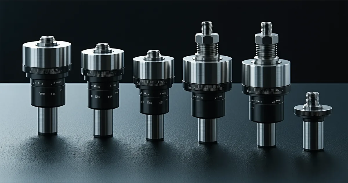
Torque density — typically expressed as peak torque in Newton-meters divided by actuator mass in kilograms — is the headline figure that humanoid robot designers use to compare compact joint actuators. But peak Nm/kg is only one number on a more complex surface. Continuous torque density, peak-to-continuous ratio, thermal limits, gear reduction architecture, and magnet grade all interact to produce the real operating envelope. This post documents our benchmarking methodology and summarizes what the data looks like across the major actuator classes available in the 100–480 mm OD range as of early 2025.
We're not saying torque density is the only axis that matters — it isn't. Backdrivability, encoder resolution, latency, and firmware interface quality all determine whether an actuator is usable in a given application. But torque density is the gateway filter. If an actuator fails to meet the minimum threshold for your joint, the rest of its spec sheet is irrelevant.
Benchmark Methodology
We characterized actuators on an in-house dynamometer running a Magtrol HD-815 torque transducer with a rated range of 0–200 Nm and a stated accuracy of ±0.25% full scale. All measurements are reported at the output shaft after the integrated gearbox (where applicable), with actuator mass including all integrated electronics, housing, output flange, and gearbox, but excluding external cables and connectors beyond 50 mm from the housing.
Two torque values are reported per actuator class:
- Peak torque: maximum output sustained for 5 seconds at T_ambient = 25 °C from cold, without thermal fault
- Continuous torque: thermal equilibrium torque at T_ambient = 25 °C after 30 minutes of constant-load operation
Mass is weighed on a calibrated bench scale including all integrated electronics, housing, flange, and gearbox — excluding cables beyond 50 mm. For third-party actuator ranges, figures are aggregated from publicly available datasheets; where datasheets omit a thermal qualification on continuous torque, we note this and apply a conservative estimate.
Actuator Class Overview
There are five distinct actuator architectures commonly evaluated for humanoid joint use. They differ in gearbox topology, motor type, and thermal architecture in ways that directly affect the torque density achievable:
1. BLDC + Harmonic Drive (Strain Wave Gear)
This is the dominant architecture for humanoid joint actuators in the 100–300 mm OD range. A high-speed BLDC motor (typically 14–28 poles) drives a harmonic drive reducer at ratios between 50:1 and 160:1. The harmonic drive contributes excellent torque density at the gearbox level — strain wave gears achieve peak torque-to-weight ratios above 100 Nm/kg at the gear assembly level — and enables compact axial packaging. The flex-spline compliance also provides a degree of mechanical torque filtering that benefits force control applications.
Measured peak torque density range (published datasheets, aggregated): 25–55 Nm/kg across available units in the 120–300 mm OD class. Continuous torque density: 8–22 Nm/kg. The large peak-to-continuous ratio (2.5–4:1 is typical) reflects the harmonic drive's mechanical advantage at absorbing peak loads, but continuous torque is thermally limited by the BLDC stator's I²R dissipation in the compact housing.
The TK-120 measured on our dyno: 42 Nm peak / 1.8 kg = 23.3 Nm/kg peak, 18 Nm continuous / 1.8 kg = 10.0 Nm/kg continuous. The TK-240: 95 Nm peak / 3.4 kg = 27.9 Nm/kg peak, 42 Nm continuous / 3.4 kg = 12.4 Nm/kg continuous.
2. BLDC + Planetary Gearbox
Planetary gearboxes offer higher efficiency than harmonic drives (typically 92–97% vs. 75–85% for harmonic drives) but at the cost of larger radial envelope and reduced gear ratio per stage. A single planetary stage achieves ratios of 3:1 to 10:1; two-stage arrangements reach 20:1 to 100:1. The efficiency advantage means less heat from gear losses and improved backdrivability, but the larger envelope pushes mass up, reducing peak torque density relative to harmonic drive designs of equivalent output torque.
Measured peak torque density range (aggregated datasheets): 15–35 Nm/kg. Continuous torque density: 6–16 Nm/kg. Higher continuous density fraction relative to peak compared to harmonic drives, because efficiency losses are lower. For applications where continuous load matters more than peak (legged locomotion stance phase, sustained load carrying), planetary gearbox actuators can be more thermally efficient even at lower peak density.
3. BLDC + Cycloidal Drive
Cycloidal reducers have seen significant interest for humanoid applications because they achieve harmonic-drive-like compactness with efficiency closer to planetary gearboxes in practice (measured 80–92% depending on ratio and lubrication). The eccentric bearing arrangement requires multi-lobe cam profiles and is more difficult to manufacture at tight tolerances than either planetary or harmonic alternatives, which affects cost and availability at small quantities.
Aggregated datasheet torque density range: 20–45 Nm/kg peak. Continuous density data is less commonly published by suppliers; where available, continuous-to-peak ratios run 30–45%, slightly better than harmonic drives. The torque ripple profile of cycloidal drives differs from harmonic drives — multiple equally-spaced contact lobes produce higher-frequency but lower-amplitude ripple, which is easier to cancel with FOC harmonic injection at the current controller.
4. Direct-Drive BLDC (Zero or 1:1 Transmission)
Direct-drive actuators eliminate gearbox losses and provide excellent backdrivability and force transparency. The trade-off is severe: to produce the same output torque as a geared actuator, the motor must generate that torque directly, which requires significantly higher stator mass and copper volume. At the 100–200 mm OD scale, direct-drive peak torque density typically ranges from 3–12 Nm/kg — substantially below geared alternatives. The continuous-to-peak ratio is better (often 50–70%) because there are no gear losses to drive I²R heating, but the absolute values are low.
Direct-drive makes sense for applications where force transparency and zero backlash dominate the requirements: haptic interfaces, force-controlled wrist joints, ankle exoskeletons with high compliance demands. It is rarely the right choice for hip or knee joints on a full-scale humanoid where gravity compensation requires sustained torques above 30 Nm.
5. Quasi-Direct-Drive (QDD)
QDD actuators (gear ratios 5:1–20:1) sit between direct-drive and high-ratio geared designs. Peak torque density: 12–28 Nm/kg; continuous: 5–14 Nm/kg. The flat peak-to-continuous ratio (near 2:1) makes thermal modeling straightforward. The tradeoffs are larger motor envelope for equivalent output torque, and higher iron losses at walking speed due to elevated back-EMF at low gear ratio. QDD is well-suited for ankle and wrist joints where force transparency matters more than peak torque density.
Magnet Grade and Its Measurable Effect
BLDC motor torque constant Kt scales with air-gap flux density, which scales with magnet grade. Moving from N42 to N52 sintered NdFeB magnets increases remnant flux density from approximately 1.29 T to 1.45 T — a 12% improvement. In a fixed motor geometry, this translates to roughly 10–12% higher Kt, which means 10–12% higher torque per amp with the same copper losses.
For a compact joint actuator where thermal limits cap continuous torque, this 12% gain in Kt directly translates to 12% higher continuous torque density at equivalent dissipation. The cost difference between N42 and N52 at small-batch procurement is approximately 15–25% per magnet assembly. For high-performance joints where mass budget is tight, N52 is justified. For lower-priority joints (wrist, finger), N42 is adequate.
N52 magnets also have a lower maximum operating temperature (80°C vs. 120°C for N42H grade), which matters when the magnet assembly is inside the stator and exposed to winding heat. High-temperature N52 grades (N52H or N52SH) extend this to 120°C and 150°C respectively, at additional cost. The TK-240 uses N52H to maintain the high Kt without demagnetization risk at the thermal limits the stator can reach during peak operation.
Peak-to-Continuous Ratio: The Number Datasheets Underreport
Peak Nm/kg is easy to publish because it looks impressive and can be measured from a cold actuator in a 5-second burst. Continuous torque density requires a 30-minute dyno run and honest reporting of the thermal equilibrium condition. Many available datasheets for compact actuators in this category report only peak torque, or report continuous torque without specifying the ambient temperature and thermal equilibrium condition. This makes direct comparison misleading.
The ratio that matters for actuator selection is the peak-to-continuous ratio at your expected duty cycle and ambient temperature. A high-ratio geared harmonic drive actuator with a 4:1 peak-to-continuous ratio is excellent for dynamic tasks like sprinting or stair climbing, where peak torque events are brief and thermal recovery occurs between cycles. It is a poor fit for a sustained load-bearing posture where the joint must hold 90% of peak torque continuously — the winding will derate rapidly.
We publish both values for every TK model. The continuous torque figures in our datasheets are measured at thermal equilibrium with T_ambient = 25 °C and separately at 45 °C to reflect enclosed-chassis operating conditions. We also publish the derating slope (Nm per degree C ambient rise) as a design input parameter, not just a footnote.
What Changes Between 2024 and 2025
Two trends have moved the state of compact actuator torque density measurably over the past 18 months:
Higher pole counts. Moving from 14-pole to 20-pole or 28-pole BLDC stator designs reduces cogging torque amplitude and increases torque constant at equivalent winding length, allowing higher continuous torque density without changing motor OD. The tradeoff is higher iron losses at speed and increased switching frequency demands on the FOC controller. At 28 poles with a 10,000 RPM motor, the electrical frequency at full speed reaches 2.3 kHz — the FOC current controller must run at a minimum of 4× electrical frequency to close the current loop effectively, pushing the PWM switching frequency above 10 kHz.
Better thermal interface materials. The winding-to-housing gap is the dominant thermal resistance in compact actuators. Gap-fill materials with conductivity above 6 W/(m·K) — up from 1–2 W/(m·K) for standard silicone pads — reduce Rth,winding-housing by 30–45%, directly improving continuous torque density without changing motor geometry. Phase-change TIMs that liquefy at operating temperature fill micro-gaps the mechanical press-fit leaves open, yielding a measurable 15–20% improvement in continuous torque density from the same motor assembly.
Design Guidance: Matching Actuator Class to Joint Requirements
A useful framing for humanoid joint selection: map each joint to a position on the peak-vs-continuous torque requirement plane, then overlay the actuator class capability regions.
| Joint | Peak Torque Req. | Continuous Torque Req. | Recommended Arch. |
|---|---|---|---|
| Hip (sagittal) | 60–120 Nm | 30–55 Nm | BLDC + Harmonic or Cycloidal |
| Knee | 80–150 Nm | 20–60 Nm | BLDC + Harmonic (high ratio) |
| Ankle | 40–90 Nm | 15–40 Nm | QDD or Harmonic (lower ratio) |
| Shoulder (ab/ad) | 30–70 Nm | 10–25 Nm | BLDC + Harmonic or Planetary |
| Elbow | 20–50 Nm | 8–20 Nm | BLDC + Harmonic (compact OD) |
| Wrist | 10–25 Nm | 3–10 Nm | QDD or Direct-Drive (force transparency) |
The ranges above are based on publicly available humanoid locomotion research (bipedal walking at 1.2–1.6 m/s, stair ascent, manipulation with payloads up to 5 kg). They are a starting bracket, not guarantees — your platform's mass distribution and gait parameters will shift them. Validate against your specific dynamics model before locking actuator selection.
The central lesson from this benchmarking exercise: no single actuator architecture is optimal across all joints. A humanoid built with uniform actuators across 20–28 DOF is over-engineered at the wrist and under-specced at the knee. The most thermally and mass-efficient designs use at least three actuator classes, each matched to the peak and continuous torque demands of its specific joint group — a decision that is far cheaper to make at the selection stage than to revisit after the mechanical layout is fixed.