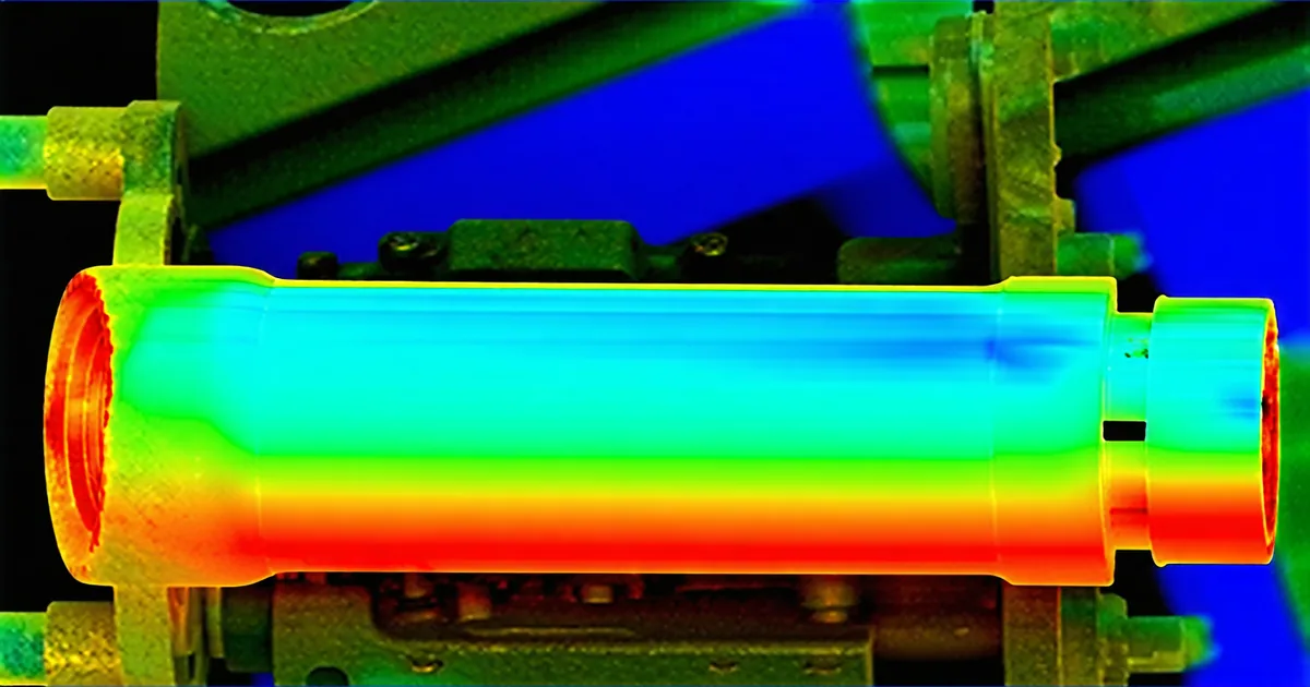
Compact joint actuators are thermal puzzles. You are packing a high-flux BLDC motor, a harmonic drive reducer, an encoder, and a power stage into a cylindrical housing typically 120–240 mm in outer diameter. Heat has almost nowhere to go. Understanding — and designing around — thermal derating is not optional engineering; it is the difference between a joint that operates continuously at rated torque and one that faults after twelve minutes of a gait cycle.
This post covers how we characterize the thermal behavior of the TK series, how we derive the derating curves published in the datasheet, and how the firmware thermal-protection loop uses RTD and NTC sensor feedback to enforce those curves in real time.
Where the Heat Actually Comes From
Two dominant loss mechanisms drive winding temperature in a BLDC joint actuator: copper losses and iron losses.
Copper losses follow the I²R relationship exactly. If you are commanding a continuous torque of 18 Nm on a TK-120 with a motor constant Kt near 0.14 Nm/A, you are drawing roughly 128 A at the motor terminals in a 100:1 gearbox configuration — actually closer to 1.28 A after the gear reduction. Phase resistance on the stator is around 0.08 Ω per phase in a typical three-phase wye configuration at that winding count. The I²R loss per phase is modest at light loads, but it scales with the square of current: doubling torque demand quadruples winding copper losses. This nonlinearity matters when you consider peak torque profiles during a step or catch event in bipedal locomotion.
Iron losses — hysteresis and eddy current losses in the stator laminations — scale with switching frequency and flux density. At 400 Hz FOC bandwidth, iron losses are non-negligible, especially at high pole counts. Our TK-120 uses a 14-pole stator, which reduces back-EMF ripple and torque ripple but increases iron loss contribution at the FOC switching frequency. Iron losses are roughly constant with torque level at a given speed, unlike copper losses — which means they matter more at low-load, high-speed operation.
The harmonic drive itself contributes a smaller but real thermal load through mesh friction. At 100:1 ratio under dynamic loading, the flex-spline mesh efficiency sits between 75–85% depending on lubrication state and temperature — the remaining power dissipates as heat directly into the gearbox housing, which shares thermal mass with the motor.
Measuring Thermal Resistance: Rth and the Time Constant
Thermal resistance Rth characterizes how many degrees of winding temperature rise result from one watt of continuous dissipation. For a compact actuator, we define two values: Rth,winding-housing (winding to the actuator housing) and Rth,housing-ambient (housing to ambient air). The product Rth,winding-ambient = Rth,wh + Rth,ha gives the total thermal resistance from winding to ambient.
Measuring this requires a controlled dyno setup. We run the actuator at a fixed torque load until thermal equilibrium, log Twinding (via a PT100 RTD embedded in the stator end-turns) and Tambient (via a calibrated NTC on the housing exterior). From a typical run at 12 Nm continuous on the TK-120 in still air:
- Steady-state Twinding: 112 °C
- Tambient: 25 °C
- Estimated total dissipation at that torque: 18 W (copper + iron + gear friction)
- Rth,winding-ambient: (112 - 25) / 18 ≈ 4.8 °C/W
The thermal time constant τ of the winding — how long it takes to reach 63% of steady-state temperature rise — is a function of winding thermal mass divided by conductance. For the TK-120 stator assembly, τ sits around 90–120 seconds in still air. This has direct implications for peak torque rating: the actuator can sustain torques well above continuous rating for durations shorter than τ without exceeding the winding insulation class limit (Class F: 155 °C).
Deriving the Derating Curve
The derating curve published in the TK-120 datasheet is a plot of maximum continuous torque versus Tambient. It is not a marketing number — it is a derived constraint from three fixed values: winding insulation class temperature limit, measured Rth,winding-ambient, and the measured power dissipation coefficient at rated torque.
The derivation is straightforward. Let Tmax = maximum allowable winding temperature (we derate to 140 °C, 15 °C below Class F limit, as a reliability margin). Let P(τrated) be the total dissipation at rated continuous torque. Then:
T_winding = T_ambient + R_th × P(τ)

Rearranging for max allowable dissipation at a given ambient:
P_max(T_ambient) = (T_max - T_ambient) / R_th

And since P ∝ τ² (copper losses dominate at the torques relevant to derating):
τ_continuous_max(T_ambient) = τ_rated × sqrt(P_max / P_rated)
At T_ambient = 25 °C, the TK-120 delivers 18 Nm continuously. At T_ambient = 55 °C — a realistic temperature inside a robot chassis with a loaded battery pack nearby — the maximum continuous torque drops to roughly 13.4 Nm. That is a 26% derating for a 30 °C ambient increase. If your robot chassis runs warm, you need to account for this in your joint torque budget from day one of mechanical design.
Peak Torque Is a Different Curve
The peak torque rating (e.g. 42 Nm for the TK-120 at 25 °C ambient) is limited by two independent ceilings, whichever is reached first:
- Current limit in the power stage (absolute phase current maximum)
- Time-averaged winding temperature — the thermal time constant determines how long the peak can be sustained
Peak torque derating with ambient temperature is steeper than continuous derating, because at peak current, I²R losses are much larger and the winding approaches Tmax faster. At T_ambient = 55 °C, the TK-120 can sustain 42 Nm for approximately 4 seconds before the firmware thermal protection intervenes. At 25 °C ambient, the same peak can hold for closer to 12 seconds. This is the practical constraint for stair-climbing, recovery from stumble, or pick-and-place with heavy payload.
Firmware Thermal Protection: The NTC Feedback Loop
The TK firmware implements thermal protection at the current controller level — not as a simple over-temperature cutoff, but as a continuous derating function applied to the current limit register.
Two temperature inputs feed the protection loop. The primary sensor is a PT100 RTD mounted in the stator end-turns, giving a direct Twinding measurement with good thermal coupling (response time approximately 2–4 seconds). The secondary is an NTC thermistor on the power stage PCB, monitoring Tambient,local inside the housing. The RTD is more accurate for winding temperature; the NTC responds faster to transient events like a sudden increase in ambient (hot environment insertion) and is also used to compute brake current limits for emergency stop.
The derating function applied to the current limit Ilim is piecewise linear:
if T_winding < T_derate_onset (default 120°C):
    I_lim = I_max

if T_derate_onset ≤ T_winding < T_max (140°C):
    I_lim = I_max × (T_max - T_winding) / (T_max - T_derate_onset)

if T_winding ≥ T_max:
    I_lim = I_brake_hold  # minimum to maintain brake engagement
    fault_bit |= THERMAL_FAULT
The brake current limit Ibrake_hold — roughly 8–12% of Imax — is the minimum current required to hold the joint stationary against gravity when the actuator has entered thermal fault state. Cutting current entirely is not safe for a loaded joint; the firmware maintains just enough to prevent uncontrolled drop while reporting the fault to the controller. This behavior is configurable via CoE SDO register 0x4012 on the EtherCAT variant.
Practical Scenario: Humanoid Torso Joint in Continuous Assembly Task
A university research group testing a bipedal platform with TK-240 actuators at the hip joints ran into a thermal derating event during a repetitive pick-and-place task. The platform was operating in a lab space where the robot chassis interior reached approximately 42 °C during operation — warmer than the standard characterization ambient of 25 °C — due to battery management electronics dissipating heat nearby.
The hip joint was programmed to sustain 38 Nm during stance phase, repeated at a 1.2 Hz gait cycle. At 25 °C ambient, 38 Nm is within continuous rating for the TK-240 (42 Nm continuous). At 42 °C internal ambient, the effective continuous rating had derated to approximately 36.8 Nm. The firmware began progressively reducing Ilim after roughly 8 minutes of operation, causing the joint to fall short of commanded torque mid-stance.
The fix was straightforward: add forced airflow across the actuator housing (a small 40mm fan moving 3 CFM across the finned housing reduced Rth,housing-ambient by approximately 35%), and reduce the continuous stance torque command to 35 Nm with an upper limit compensation strategy. The RTD telemetry — available as a ROS 2 topic on the TK firmware — was instrumental in diagnosing the root cause without needing thermal camera access to an enclosed robot chassis.
What the Derating Curves Don't Tell You
We're not saying derating curves are a complete thermal model — they are a steady-state simplification. The curves assume thermal equilibrium and constant ambient. A joint actuator in a real robot experiences neither. Tambient changes as the chassis warms. Torque demand varies with gait phase, load, and terrain. The winding's actual temperature traces a trajectory through the derating map, not a single operating point.
For demanding duty cycles, the right tool is a lumped-parameter thermal model of the actuator: winding thermal capacitance, winding-to-housing conductance, housing-to-ambient conductance, and a heat source term proportional to I²R + iron loss + gear friction. This can be implemented as a simple observer in the controller and used to generate predictive current limits before the RTD registers a fault condition. We have an application note on this approach available on the resources page.
What the derating curve does tell you — clearly and without interpretation — is the safe continuous operating envelope. If your duty cycle keeps you inside it, you will never see a thermal fault. Engineers who build their trajectory planners to respect the derating map do not debug thermal events at 2 AM. Those who treat the continuous rating as a fixed number independent of ambient find out exactly where it breaks.
RTD vs. NTC: Sensor Selection for the Monitoring Loop
A frequent question: can the NTC on the housing exterior replace the RTD in the stator for thermal protection? No. The NTC gives Thousing, not Twinding. During a peak torque transient, the winding-to-housing temperature delta can reach 30–50 °C. The housing temperature lags winding temperature by 20–40 seconds under step load changes. An NTC-only scheme is structurally late — it will react after the winding has already exceeded the insulation class limit.
The PT100 RTD embedded in the stator end-turns couples directly to winding temperature. Its linear response characteristic is no liability at these thermal time constants. For closed-loop thermal protection, the RTD is the primary sensor. The NTC covers housing overtemperature and brake current limit calculation, and serves as a cross-check: if the RTD reads below the NTC housing temperature, the firmware flags a sensor fault and falls back to a conservative NTC-derived limit.