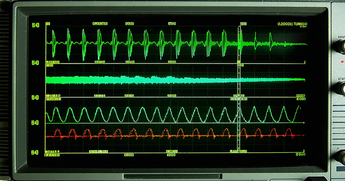
Field-oriented control on a BLDC actuator is not plug-and-play. The textbook derivation of the DQ-axis current controller assumes an ideal motor model, a perfect encoder, and infinite bus voltage. Real high-torque joints violate all three. This post works through how we tune the FOC stack on the TK-120 and TK-240 — not as a theoretical exercise, but as a sequence of decisions with measurable consequences in torque ripple and thermal behavior.
Why FOC in the First Place: BLDC vs. PMSM Commutation Modes
There is persistent confusion about the distinction between BLDC and PMSM when it comes to commutation strategy. The hardware is often identical — a permanent-magnet synchronous machine with three phases. The difference is in how the drive firmware commutates them.
Trapezoidal commutation (what most "BLDC" drives do) is computationally cheap and works at high speeds, but it applies phase current in discrete 60-degree blocks. That discrete switching produces torque ripple that is audible in quiet environments and measurable on any torque transducer. At a gear ratio of 100:1, whatever ripple exists at the motor shaft gets attenuated by the gearbox stiffness — but it does not disappear. In precision manipulation tasks, position-control loops can excite those torque ripple frequencies into resonance with joint compliance.
Sinusoidal commutation (true FOC / PMSM control) maintains continuous, smooth current injection across all three phases simultaneously. Using the Clarke and Park transforms to project three-phase quantities into the rotating DQ reference frame, the current controller sees two DC quantities — I_d (flux-producing) and I_q (torque-producing) — instead of three sinusoidal time-varying signals. This makes PI tuning tractable and bandwidth maximization achievable.
We're not saying trapezoidal commutation is wrong for every application. For a high-speed pump or a fan drive, trapezoid is fine and simpler to implement. But for a joint actuator operating at low speeds under high load — exactly the regime of a humanoid knee joint — FOC with space vector modulation is the correct commutation mode.
The DQ Axis Current Loop: Gain Selection and Bandwidth Targets
The inner current loop is the foundation everything else rests on. If current bandwidth is too narrow, the outer velocity and position loops cannot be stiffened without losing phase margin. If gain is too high, the loop rings at switching harmonics and corrupts the motor model estimates.
For the TK-120, operating at a 24 V bus with a motor inductance around 180 µH per phase and winding resistance near 0.45 Ω, the current loop crossover frequency target is 2–3 kHz. At a 20 kHz PWM frequency, that crossover gives a healthy decade of attenuation above the switching frequency. The PI gains for the D and Q axes are not necessarily identical — particularly when operating near voltage saturation, the decoupling terms between D and Q become significant.
// TK-120 current loop — initial tuning parameters
// Motor: Ld = Lq = 180 µH, Rs = 0.45 Ω, pole pairs = 7
// Bus: 24V nominal, 20 kHz PWM

float Kp_dq   = 0.82f;   // proportional gain (A/V)
float Ki_dq   = 1250.0f; // integral gain (A/V/s)
float Kp_d    = Kp_dq;
float Ki_d    = Ki_dq;
float Kp_q    = Kp_dq;
float Ki_q    = Ki_dq;

// Feed-forward decoupling (critical above 500 RPM)
float v_d_ff  = -omega_e * Lq * I_q;
float v_q_ff  =  omega_e * Ld * I_d + omega_e * lambda_pm;
// lambda_pm (flux linkage) estimated from no-load back-EMF characterization
The integral gain deserves close attention. Setting Ki based purely on a Ziegler-Nichols step response gives you a number that often performs well at room temperature but drifts as motor resistance rises 20–30% at thermal steady-state. We run the characterization at 60°C winding temperature and treat the cold values as initial conditions, not final ones.
Anti-Windup: the Detail That Matters Most at Voltage Saturation
High-torque joints regularly hit voltage saturation. When the commanded torque exceeds what the available bus voltage can deliver — either during peak acceleration or during braking while the bus voltage is elevated by regen — the PI integrator accumulates error that has no corresponding actuator output. When the saturation clears, the integrator discharges through the plant as an overshoot spike.
In a knee joint, that spike arrives as an unintended torque pulse. At best it degrades position tracking. At worst, in a force-controlled mode, it constitutes an unintended force event on a human-adjacent surface.
We implement back-calculation anti-windup rather than integrator clamping. The difference is subtle but important: integrator clamping simply stops accumulating when output saturates, which leaves a finite accumulated value that causes a delayed overshoot after saturation clears. Back-calculation continuously corrects the integrator state by the saturation error scaled by a tracking time constant Tt:
// Back-calculation anti-windup
// Tt should be set between Ti and sqrt(Td*Ti) for optimal recovery
// For our purely PI controller: Tt = Ti / 5 (empirical, fast recovery)

float saturation_error = v_out_clamped - v_out_unclamped;
integrator_state += (Ki_dq * error + saturation_error / Tt) * dt;
With back-calculation tuned correctly, the integrator state tracks the achievable output throughout the saturation period. Recovery is monotonic with no overshoot. The tradeoff is that you need to know the actual actuator output limits precisely — which requires characterizing bus voltage droop under peak current draw, not assuming a constant 24 V rail.
Encoder Phase Alignment and Its Impact on DQ Accuracy
A tuned current controller running on misaligned encoder phase produces a systematic torque error that masquerades as poor gain tuning. The D-axis should carry zero torque-producing current at steady state — it should only carry magnetizing current (and zero for surface-mount PMs). If phase alignment is off by 10–15 electrical degrees, I_q contaminates I_d and vice versa. The result is a motor that feels sluggish and runs hotter than expected.
We align using a locked-rotor procedure: command a fixed D-axis current of about 20% rated, let the rotor settle, then record the encoder count at that electrical zero. This takes roughly 800 ms to settle, longer on high-inertia gearbox systems where the rotor can't freely find its equilibrium through backdrive.
A university lab in Pittsburgh working with an early TK-120 prototype reported persistent torque oscillations at low speed. After walking through their firmware configuration, the misalignment register had never been written — the default value was non-zero from a flash initialization artifact. Correcting the alignment offset eliminated the oscillation entirely. No gains were changed.
The lesson: characterize alignment before you characterize gains. A properly aligned motor with moderately tuned gains outperforms a perfectly tuned motor on a misaligned encoder.
Observer-Based Estimation for Sensorless Fallback
The TK firmware includes an observer-based velocity and position estimator for two purposes: first, as a sanity-check cross-reference against the primary 19-bit encoder; second, as a fallback mode if the encoder cable is compromised. For a joint actuator in a humanoid platform, encoder cable failure mid-operation should trigger a graceful torque ramp-down rather than an immediate open-loop fault that causes a limb to freefall.
We use a sliding-mode observer on the back-EMF, not an extended Kalman filter. The sliding-mode observer is computationally lighter and more predictable in its transient behavior on the STM32. The EKF requires continuous covariance propagation that introduces inconsistent latency at higher update rates. For the bandwidth we target (400 Hz FOC loop), the sliding-mode observer is the correct choice.
The observer is not rated for primary control below 50 RPM mechanical. Below that speed, back-EMF amplitude is insufficient for reliable estimation. In humanoid applications, slow-speed precision positioning still requires encoder feedback — the observer handles the recovery, not the task itself.
Gain Margin and Stability at High Gear Ratios
Adding a harmonic drive between the current-controlled motor and the output flange introduces torsional compliance into the mechanical plant. The harmonic drive flex-spline acts as a torsional spring, and at high torque-loading the resonant frequency of that spring-inertia system can fall within the bandwidth of the outer position loop — sometimes within the bandwidth of the current loop itself if gains are aggressive.
For the TK-120 at 100:1 gear ratio with typical arm-segment inertia attached, the torsional resonance of the harmonic drive flex-spline appears between 80–140 Hz mechanical. A current loop crossover at 2.5 kHz has 18 dB of gain margin above this frequency assuming a nominal motor model. But when operating near voltage saturation, the effective loop gain drops and margin decreases. Design for the worst case: measure gain margin with the bus at 20 V, at rated current, at 60°C.
If you're pushing current bandwidth above 3 kHz on a compact actuator, add a notch filter at the identified torsional resonance. A second-order IIR at 120 Hz mechanical — which is 840 Hz electrical at 7 pole pairs — with a Q of 6.0 and depth of -18 dB provides adequate resonance suppression without meaningfully degrading step response below 50 Hz.
Practical Starting Points for the TK Series
These are the register settings we ship from the factory for the TK-120. They are starting points, not finals. Any motor installation with a different attached inertia or gearbox compliance will need iteration.
// TK-120 factory FOC defaults (firmware v1.4.x)
// All values in SI units unless noted

FOC_CURRENT_LOOP_KP   = 0.82    // [V/A]
FOC_CURRENT_LOOP_KI   = 1250    // [V/A/s]
FOC_AW_TRACKING_TC    = 0.0008  // [s] back-calculation Tt
FOC_ALIGN_ELEC_OFFSET =
FOC_CROSSOVER_HZ_TARGET = 2500  // [Hz] verify with Bode sweep
FOC_NOTCH_FREQ_HZ     = 0       // [Hz] set if resonance identified
FOC_NOTCH_Q           = 6.0
FOC_SVPWM_OVERMOD     = 0       // 0=linear region, 1=overmod permitted
Space vector modulation overmodulation (SVPWM_OVERMOD = 1) extends effective voltage utilization by about 15% by allowing the output vector to enter the non-linear region of the hexagon. It helps at peak torque demand, but it introduces 5th and 7th harmonic current injection that slightly elevates torque ripple. For manipulation tasks requiring fine torque resolution, keep overmodulation disabled. Enable it only for peak-torque emergency operations.
FOC tuning is iterative. The sequence that works: align encoder, set modest gains, verify stability across the operating speed range, tighten gains until resonance appears, back off 6 dB, add notch if needed. There is no shortcut. But the reward — a current loop that tracks a sinusoidal reference at 2.5 kHz with less than 5° phase lag and sub-1% torque ripple — makes every manipulation trajectory smoother from the first test run.