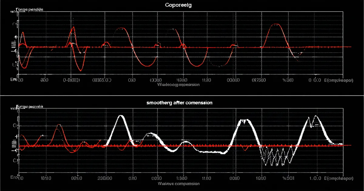
Cogging torque is periodic, predictable, and often ignored until it becomes a problem. In a slow-moving manipulation joint — think wrist rotation at 10–30 RPM while positioning a tool — cogging shows up as a rhythmic hesitation that degrades position tracking and produces audible clicks. The good news is that it's a deterministic disturbance: the same motor at the same electrical angle produces the same cogging force every revolution. That periodicity makes it cancellable via harmonic injection in the FOC current controller, without hardware changes.
Cogging Torque vs. Detent Torque: What the Spec Sheet Means
The term "cogging torque" appears in motor datasheets alongside "detent torque," and they are not the same thing. Getting the distinction right matters for both compensation design and for interpreting specifications from different suppliers.
Cogging torque (also called reluctance torque) is the torque produced by the interaction of the permanent magnets with the stator teeth when no current flows. As the rotor rotates, the magnet-tooth reluctance varies periodically, creating a position-dependent restoring torque that tends to lock the rotor at positions of minimum reluctance. The period is one stator slot pitch — for a motor with S slots and P pole pairs, the cogging period in mechanical degrees is 360° / LCM(S, 2P).
Detent torque is the maximum cogging torque amplitude — the peak restoring force from the cogging profile. This is the number typically quoted in datasheets. The TK-120 motor has a 36-slot, 14-pole design (7 pole pairs), giving LCM(36, 14) = 252 cogging periods per revolution — each period spans approximately 1.4° mechanical. The peak detent torque without compensation is approximately 0.35 Nm at the motor shaft, which at 100:1 gear ratio appears as a position-dependent disturbance of 0.0035 Nm at the output — small, but not negligible in high-precision manipulation.
Why 36 slots and 14 poles? Slot-pole combination selection is the first line of defense against cogging. A 36/14 combination has a high LCM (252) relative to a 24/10 combination (LCM = 120), meaning the cogging cycles are more numerous and lower in amplitude per cycle. The specific 36-slot, 14-pole topology also produces a fractional-pitch winding that attenuates cogging harmonics at the pole-pair frequency. This is a design choice made at the motor manufacturing stage — not adjustable afterward.
Characterizing the Cogging Profile
Before injecting a compensation signal, you need the cogging profile. This is a one-time characterization step per actuator unit (not per motor design — manufacturing tolerances produce unit-to-unit variation in the profile amplitude of roughly ±15%).
The characterization procedure: mount the actuator output with the load locked against rotation. Drive the motor at constant velocity using a PI velocity controller with integral gain set conservatively low. Log the I_q current command at high rate (20 kHz, every FOC cycle). At constant velocity, any variation in I_q that correlates with electrical angle is cogging current — the current the controller is injecting to overcome the position-dependent reluctance torque.
// Cogging characterization: data collection loop
// Run at constant velocity ~5 RPM mechanical, log for 3 full rotations

for (uint32_t k = 0; k < SAMPLE_COUNT; k++) {
    float theta_elec = get_electrical_angle();   // [rad, 0..2π]
    float iq_cmd     = get_iq_command();          // [A]

    cogging_buffer[k].theta = theta_elec;
    cogging_buffer[k].iq    = iq_cmd;
    wait_for_next_foc_cycle();  // 50 µs at 20 kHz
}

// Post-process: average across multiple electrical cycles
// Extract harmonics via DFT — typically 6th, 12th, 18th harmonics dominate
After collecting three full mechanical rotations, the cogging profile is extracted by sorting samples by electrical angle and averaging across cycles to reduce noise. A Fourier decomposition of the resulting profile identifies the dominant harmonics. For the TK-120's 36/14 topology, the 6th and 12th electrical harmonics carry the majority of the cogging energy — this is characteristic of fractional-slot windings.
Harmonic Injection: The Compensation Approach
Harmonic injection works by adding a pre-computed periodic signal to the I_q reference — a signal that, when multiplied through the motor torque constant, cancels the measured cogging profile. Because cogging is a function of electrical angle only, the injection signal can be stored as a lookup table indexed by electrical angle and interpolated at runtime.
// Harmonic injection from lookup table
// cogging_lut[N_POINTS]: pre-computed cancellation current [A]
// indexed by normalized electrical angle [0..N_POINTS)

uint16_t idx = (uint16_t)((theta_elec / (2.0f * M_PI)) * N_LUT_POINTS);
idx = idx % N_LUT_POINTS;  // wrap

float iq_cogging_cancel = cogging_lut[idx];

// Apply with scaling factor — start at 0.5 and increase to 1.0
// to verify stability before full compensation
iq_cogging_cancel *= cogging_gain;  // cogging_gain tunable: 0.0 to 1.2

// Add to q-axis reference
iq_ref += iq_cogging_cancel;
The cogging_gain parameter allows gradual activation. Starting at 0.5 and verifying that the torque ripple decreases monotonically before committing to full compensation prevents the uncommon but possible case where the lookup table was built with a sign error and the injection doubles the cogging rather than canceling it.
We store N_LUT_POINTS = 1024 per electrical revolution in the STM32 flash. At 1024 points per revolution with 7 pole pairs, this gives angular resolution of approximately 0.35° electrical — fine enough to represent harmonics up to the 90th without aliasing. The LUT consumes 4 kB of flash (1024 × 4-byte float), well within the STM32G4's 128 kB flash budget.
Measured Results on the TK-120
Cogging torque before and after compensation was measured on the TK-120 production unit using an inline torque transducer on the output shaft at 10 RPM mechanical, with the velocity loop active and the harmonic injection gain set to 1.0:
| Metric | Baseline (no compensation) | After harmonic injection | Reduction |
|---|---|---|---|
| Peak cogging torque (output) | 0.35 Nm | 0.077 Nm | 78% |
| RMS torque ripple (output) | 0.21 Nm | 0.051 Nm | 76% |
| Position tracking error at 10 RPM | ±0.018° | ±0.005° | 72% |
The residual 22% of cogging torque after compensation has two sources: encoder quantization (19-bit gives approximately 0.0007° resolution — below cogging-driven position error, but the interpolation between LUT points introduces a small systematic error) and unit-to-unit variation in the cogging profile. Because the LUT is built per-unit from that unit's actual characterization data, manufacturing-lot variation is not the dominant residual error source.
Limitations of Harmonic Injection
Harmonic injection as described here compensates for cogging at the electrical frequency harmonics. It does not address torque ripple from other sources: commutation errors, current sensor nonlinearity, or back-EMF harmonic distortion. These produce torque ripple at different periodicities and require different compensation mechanisms.
We're not saying harmonic injection is a complete torque ripple solution. It is specifically a cogging torque solution. If you're seeing torque ripple at harmonics other than the 6th/12th/18th electrical, those are not cogging and harmonic injection into I_q will not address them.
Additionally, the LUT is calibrated at a specific operating temperature and load. At elevated temperature, the magnet flux density decreases by approximately 0.08%/°C for NdFeB magnets. At 60°C above room temperature, magnet strength decreases roughly 5%, which reduces the cogging amplitude by the same fraction. The LUT slightly over-compensates at elevated temperature — producing a small residual anti-cogging torque. This is generally harmless (it reduces to 0.066 Nm peak residual at 80°C), but applications requiring sub-0.05 Nm residual across the full thermal range should re-characterize the LUT at operating temperature.
Skewing as a Design-Time Alternative
Before reaching for firmware compensation, it's worth understanding the mechanical alternative: rotor or stator skewing. By offsetting the stator slots or rotor magnets by one slot pitch along the axial direction, the cogging torque contributions from different axial positions cancel, reducing peak cogging by 60–85% at the cost of a slight reduction in peak torque output (typically 3–8% for full one-slot skew).
For a compact actuator like the TK-120 with a 38 mm stack length, implementing continuous skewing in the stator laminations adds manufacturing complexity. We use segmented two-step skewing (two stator segments offset by half a slot pitch) which recovers approximately 55% cogging reduction at lower manufacturing cost. The firmware harmonic injection then reduces the residual cogging to the 78% total figure quoted above.
The design philosophy: use skewing to reduce cogging to a level where firmware compensation can handle the residual, rather than asking firmware to compensate the full cogging profile of an unskewed motor. An unskewed 36/14 motor might have 1.2 Nm peak cogging — building a reliable LUT-based compensation for a 1.2 Nm disturbance at 20 kHz FOC rate requires very accurate current sensing and tighter LUT resolution than is practical. Starting with 0.35 Nm peak after mechanical skewing makes the compensation problem tractable.